Browse
Dealer
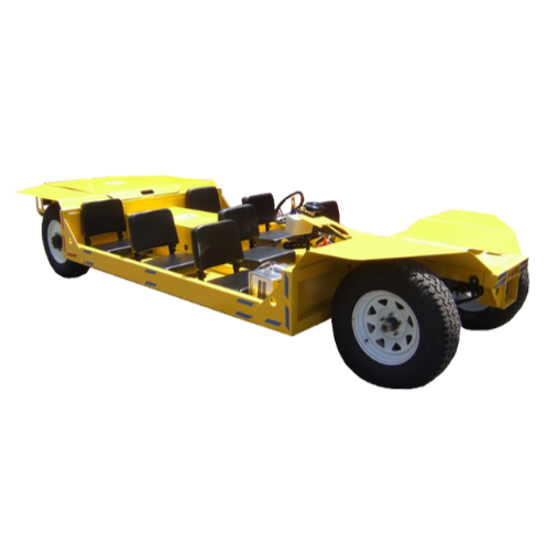
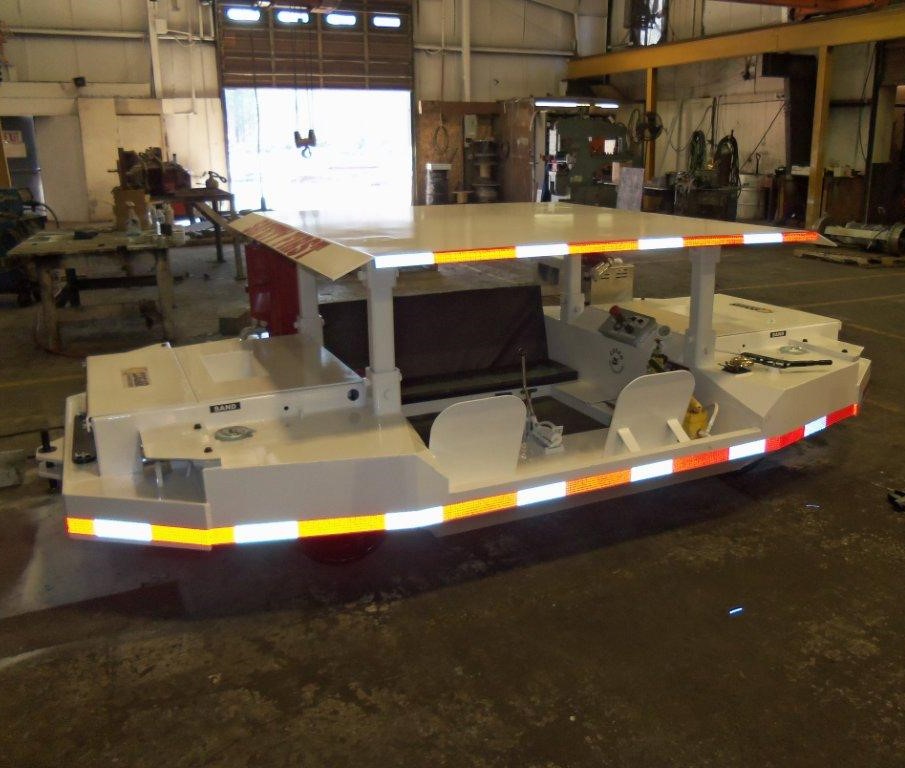
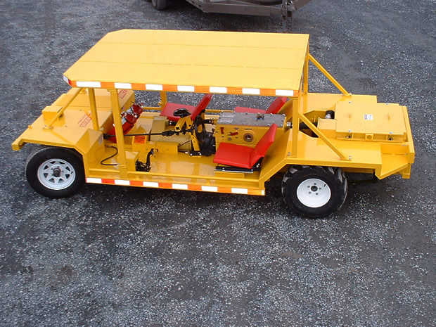
Mining Industry Electric Motors
Looking for heavy-duty electric mining vehicle motors?
D&D Motor Systems is the premier manufacturer of electric DC mining vehicle motors
in the U.S., specializing in motors for electric mining vehicle personnel carriers. Our
high-performance electric mining motors offer superior torque, enhanced thermal
capabilities, and a competitive price, all while being proudly made in the USA.
Whether you're looking for a DC or AC motor for you mining vehicle application, we
have you covered. Voltage options range from 12 to 144 volts. Additionally, we offer a
complete line of U.S. made electric DC and AC mining controllers, which function from
24 to 72 volts.
Need a Custom Electric Mining AC or DC Motor?
Mining Vehicle Motor Quick Links
| Photos | Videos | Experts |


|
Regen VS Series
Series Motor
The series motor provides high starting torque and is able to move very large shaft loads when it is first energized. Figure 12-10 shows the wiring diagram of a series motor. From the diagram you can see that the field winding in this motor is wired in series with the armature winding. This is the attribute that gives the series motor its name.
Since the series field winding is connected in series with the armature, it will carry the same amount of current that passes through the armature. For this reason the field is made from heavy-gauge wire that is large enough to carry the load. Since the wire gauge is so large, the winding will have only a few turns of wire. In some larger DC motors, the field winding is made from copper bar stock rather than the conventional round wire used for power distribution. The square or rectangular shape of the copper bar stock makes it fit more easily around the field pole pieces. It can also radiate more easily the heat that has built up in the winding due to the large amount of current being carried.
FIGURE 12-10 Electrical diagram of series motor. Notice that the series field is identified as S1 and S2.
The amount of current that passes through the winding determines the amount of torque the motor shaft can produce. Since the series field is made of large conductors, it can carry large amounts of current and produce large torques. For example, the starter motor that is used to start an automobile's engine is a series motor and it may draw up to 500 A when it is turning the engine's crankshaft on a cold morning. Series motors used to power hoists or cranes may draw currents of thousands of amperes during operation.
The series motor can safely handle large currents since the motor does not operate for an extended period. In most applications the motor will operate for only a few seconds while this large current is present. Think about how long the starter motor on the automobile must operate to get the engine to start. This period is similar to that of industrial series motors.
Series Motor Operation
Operation of the series motor is easy to understand. In Fig. 12-10 you can see that the field winding is connected in series with the armature winding. This means that power will be applied to one end of the series field winding and to one end of the armature winding (connected at the brush).
When voltage is applied, current begins to flow from negative power supply terminals through the series winding and armature winding. The armature is not rotating when voltage is first applied, and the only resistance in this circuit will be provided by the large conductors used in the armature and field windings. Since these conductors are so large, they will have a small amount of resistance. This causes the motor to draw a large amount of current from the power supply. When the large current begins to flow through the field and armature windings, it causes a strong magnetic field to be built. Since the current is so large, it will cause the coils to reach saturation, which will produce the strongest magnetic field possible.
Producing Back EMF
The strength of these magnetic fields provides the armature shafts with the greatest amount of torque possible. The large torque causes the armature to begin to spin with the maximum amount of power. When the armature begins to rotate, it begins to produce voltage. This concept is difficult for some students to understand since the armature is part of the motor at this time.
You should remember from the basic theories of magnetism that anytime a magnetic field passes a coil of wire, a current will be produced. The stronger the magnetic field is or the faster the coil passes the flux lines, the more current will be generated. When the armature begins to rotate, it will produce a voltage that is of opposite polarity to that of the power supply. This voltage is called back voltage, back EMF (electromotive force), or counter EMF. The overall effect of this voltage is that it will be subtracted from the supply voltage so that the motor windings will see a smaller voltage potential.
When Ohm's law is applied to this circuit, you will see that when the voltage is slightly reduced, the current will also be reduced slightly. This means that the series motor will see less current as its speed is increased. The reduced current will mean that the motor will continue to lose torque as the motor speed increases. Since the load is moving when the armature begins to pick up speed, the application will require less torque to keep the load moving. This works to the motor's advantage by automatically reducing the motor current as soon as the load begins to move. It also allows the motor to operate with less heat buildup.
This condition can cause problems if the series motor ever loses its load. The load could be lost when a shaft breaks or if a drive pin is sheared. When this occurs, the load current is allowed to fall to a minimum, which reduces the amount of back EMF that the armature is producing. Since the armature is not producing a sufficient amount of back EMF and the load is no longer causing a drag on the shaft, the armature will begin to rotate faster and faster. It will continue to increase rotational speed until it is operating at a very high speed. When the armature is operating at high speed, the heavy armature windings will be pulled out of their slots by centrifugal force. When the windings are pulled loose, they will catch on a field winding pole piece and the motor will be severely damaged. This condition is called runaway and you can see why a DC series motor must have some type of runaway protection. A centrifugal switch can be connected to the motor to de-energize the motor starter coil if the rpm exceeds the set amount. Other sensors can be used to de-energize the circuit if the motor's current drops while full voltage is applied to the motor. The most important part to remember about a series motor is that it is difficult to control its speed by external means because its rpm is determined by the size of its load. (In some smaller series motors, the speed can be controlled by placing a rheostat in series with the supply voltage to provide some amount of change in resistance to control the voltage to the motor.)
Figure 12-11 shows the relationship between series motor speed and armature current. From this curve you can see that when current is low (at the top left), the motor speed is maximum, and when current increases, the motor speed slows down (bottom right). You can also see from this curve that a DC motor will run away if the load current is reduced to zero. (It should be noted that in larger series machines used in industry, the amount of friction losses will limit the highest speed somewhat.)
FIGURE 12-11 The relationship between series motor speed and the armature current.
Reversing the Rotation
The direction of rotation of a series motor can be changed by changing the polarity of either the armature or field winding. It is important to remember that if you simply changed the polarity of the applied voltage, you would be changing the polarity of both field and armature windings and the motor's rotation would remain the same.
FIGURE 12-12 DC series motor connected to forward and reverse motor starter.
Since only one of the windings needs to be reversed, the armature winding is typically used because its terminals are readily accessible at the brush rigging. Remember that the armature receives its current through the brushes, so that if their polarity is changed, the armature's polarity will also be changed. A reversing motor starter is used to change wiring to cause the direction of the motor's rotation to change by changing the polarity of the armature windings. Figure 12-12 shows a DC series motor that is connected to a re-versing motor starter. In this diagram the armature's terminals are marked Al and A2 and the field terminals are marked Sl and S2.
When the forward motor starter is energized, the top contact identified as F closes so the Al terminal is connected to the positive terminal of the power supply and the bottom F contact closes and connects terminals A2 and Sl. Terminal S2 is connected to the negative terminal of the power supply. When the reverse motor starter is energized, terminals Al and A2 are reversed. A2 is now connected to the positive terminal. Notice that S2 remains connected to the negative terminal of the power supply terminal. This ensures that only the armature's polarity has been changed and the motor will begin to rotate in the opposite direction.
You will also notice the normally closed (NC) set of R contacts connected in series with the forward push button, and the NC set of F contacts connected in series with the reverse push button. These contacts provide an interlock that prevents the motor from being changed from forward to reverse direction without stopping the motor. The circuit can be explained as follows: when the forward push button is depressed, current will flow from the stop push button through the NC R interlock contacts, and through the forward push button to the forward motor starter (FMS) coil. When the FMS coil is energized, it will open its NC contacts that are connected in series with the reverse push button. This means that if someone depresses the reverse push button, current could not flow to the reverse motor starter (RMS) coil. If the person depressing the push buttons wants to reverse the direction of the rotation of the motor, he or she will need to depress the stop push button first to de-energize the FMS coil, which will allow the NC F contacts to return to their NC position. You can see that when the RMS coil is energized, its NC R contacts that are connected in series with the forward push button will open and prevent the current flow to the FMS coil if the forward push button is depressed. You will see a number of other ways to control the FMS and RMS starter in later discussions and in the chapter on motor controls.
Installing and Troubleshooting
Since a series motor has only two leads brought out of the motor for installation wiring, this wiring can be accomplished rather easily. If the motor is wired to operate in only one direction, the motor terminals can be connected to a manual or magnetic starter. If the motor's rotation is required to be reversed periodically, it should be connected to a reversing starter.
Most DC series motors are used in direct-drive applications. This means that the load is connected directly to the armature's shaft. This type of load is generally used to get the most torque converted. Belt-drive applications are not recommended since a broken belt would allow the motor to run away. After the motor has been installed, a test run should be used to check it out. If any problems occur, the troubleshooting procedures should be used.
The most likely problem that will occur with the series motor is that it will develop an open in one of its windings or between the brushes and the commutator. Since the coils in a series motor are connected in series, each coil must be functioning properly or the motor will not draw any current. When this occurs, the motor cannot build a magnetic field and the armature will not turn. Another problem that is likely to occur with the motor circuit is that circuit voltage will be lost due to a blown fuse or circuit breaker. The motor will respond similarly in both of these conditions.
The best way to test a series motor is with a voltmeter. The first test should be for applied voltage at the motor terminals. Since the motor terminals are usually connected to a motor starter, the test leads can be placed on these terminals. If the meter shows that full voltage is applied, the problem will be in the motor. If it shows that no voltage is present, you should test the supply voltage and the control circuit to ensure that the motor starter is closed. If the motor starter has a visual indicator, be sure to check to see that the starter's contacts are closed. If the overloads have tripped, you can assume that they have sensed a problem with the motor or its load. When you reset the overloads, the motor will probably start again but remember to test the motor thoroughly for problems that would cause an overcurrent situation.
If the voltage test indicates that the motor has full applied voltage to its terminals but the motor is not operating, you can assume that you have an open in one of the windings or between the brushes and the armature and continue testing. Each of these sections should be disconnected from each other and voltage should be removed so that they can be tested with an ohmmeter for an open. The series field coils can be tested by putting the ohmmeter leads on terminals Sl and S2. If the meter indicates that an open exists, the motor will need to be removed and sent to be rewound or replaced. If the meter indicates that the field coil has continuity, you should continue the procedure by testing the armature.
The armature can also be tested with an ohmmeter by placing the leads on the terminals marked Al and A2. If the meter shows continuity, rotate the armature shaft slightly to look for bad spots where the commutator may have an open or the brushes may not be seated properly. If the armature test indicates that an open exists, you should continue the test by visually inspecting the brushes and commutator. You may also have an open in the armature coils. The armature must be removed from the motor frame to be tested further. When you have located the problem, you should remember that the commutator can be removed from the motor while the motor remains in place and it can be turned down on a lathe. When the commutator is replaced in the motor, new brushes can be installed and the motor will be ready for use.
It is possible that the motor will develop a problem but still run. This type of problem usually involves the motor overheating or not being able to pull its rated load. This type of problem is different from an open circuit because the motor is drawing current and trying to run. Since the motor is drawing current, you must assume that there is not an open circuit. It is still possible to have brush problems that would require the brushes to be re-seated or replaced. Other conditions that will cause the motor to overheat include loose or damaged field and armature coils. The motor will also overheat if the armature shaft bearing is in need of lubrication or is damaged. The bearing will seize on the shaft and cause the motor to build up friction and overheat.
If either of these conditions occurs, the motor may be fixed on site or be removed for extensive repairs. When the motor is restarted after repairs have been made, it is important to monitor the current usage and heat buildup. Remember that the motor will draw DC current so that an AC clamp-on ammeter will not be useful for measuring the DC current. You will need to use an ammeter that is specially designed for very large DC currents. It is also important to remember that the motor can draw very high locked-rotor current when it is starting, so the ammeter should be capable of measuring currents up to 1000 A. After the motor has completed its test run successfully, it can be put back into operation for normal duty. Anytime the motor is suspected of faulty operation, the troubleshooting procedure should be rechecked.
DC Series Motor Used as a Universal Motor
The series motor is used in a wide variety of power tools such as electric hand drills, saws, and power screwdrivers. In most of these cases, the power source for the motor is AC voltage. The DC series motor will operate on AC voltage. If the motor is used in a hand drill that needs variable-speed control, a field rheostat or other type of current control is used to control the speed of the motor. In some newer tools, the current control uses solid-state components to control the speed of the motor. You will notice that the motors used for these types of power tools have brushes and a commutator, and these are the main parts of the motor to wear out. You can use the same theory of operation provided for the DC motor to troubleshoot these types of motors.
Shunt or Regen or SEPEX Motor
The shunt motor is different from the series motor in that the field winding is connected in parallel with the armature instead of in series. You should remember from basic electrical theory that a parallel circuit is often referred to as a shunt. Since the field winding is placed in parallel with the armature, it is called a shunt winding and the motor is called a shunt motor. Figure 12-13 shows a diagram of a shunt motor. Notice that the field terminals are marked Fl and F2, and the armature terminals are marked Al andA2. You should notice in this diagram that the shunt field is represented with multiple turns using a thin line.
FIGURE 12-13 Diagram of DC shunt motor. Notice the shunt coil is identified as a coil of fine wire with many turns that is connected in parallel (shunt) with the armature.
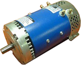
FIGURE 12-14 Typical DC shunt motor. These motors are available in a variety of sizes. This motor is a 1 hp (approximately 8 in. tall).
The shunt winding is made of small-gauge wire with many turns on the coil. Since the wire is so small, the coil can have thousands of turns and still fit in the slots. The small-gauge wire cannot handle as much current as the heavy-gauge wire in the series field, but since this coil has many more turns of wire, it can still produce a very strong magnetic field. Figure 12-14 shows a picture of a DC shunt motor.
Shunt Motor Operation
A shunt motor has slightly different operating characteristics than a series motor. Since the shunt field coil is made of fine wire, it cannot produce the large current for starting like the series field. This means that the shunt motor has very low starting torque, which requires that the shaft load be rather small.
When voltage is applied to the motor, the high resistance of the shunt coil keeps the overall current flow low. The armature for the shunt motor is similar to the series motor and it will draw current to produce a magnetic field strong enough to cause the armature shaft and load to start turning. Like the series motor, when the armature begins to turn, it will produce back EMF. The back EMF will cause the current in the armature to begin to diminish to a very small level. The amount of current the armature will draw is directly related to the size of the load when the motor reaches full speed. Since the load is generally small, the armature current will be small. When the motor reaches full rpm, its speed will remain fairly constant.
Controlling the Speed
When the shunt motor reaches full rpm, its speed will remain fairly constant. The reason the speed remains constant is due to the load characteristics of the armature and shunt coil. You should remember that the speed of a series motor could not be controlled since it was totally dependent on the size of the load in comparison to the size of the motor. If the load was very large for the motor size, the speed of the armature would be very slow. If the load was light compared to the motor, the armature shaft speed would be much faster, and if no load was present on the shaft, the motor could run away.
The shunt motor's speed can be controlled. The ability of the motor to maintain a set rpm at high speed when the load changes is due to the characteristic of the shunt field and armature. Since the armature begins to produce back EMF as soon as it starts to rotate, it will use the back EMF to maintain its rpm at high speed. If the load increases slightly and causes the armature shaft to slow down, less back EMF will be produced. This will allow the difference between the back EMF and applied voltage to become larger, which will cause more current to flow. The extra current provides the motor with the extra torque required to regain its rpm when this load is increased slightly.
The shunt motor's speed can be varied in two different ways. These include varying the amount of current supplied to the shunt field and controlling the amount of current supplied to the armature. Controlling the current to the shunt field allows the rpm to be changed 10-20% when the motor is at full rpm.
This type of speed control regulation is accomplished by slightly increasing or decreasing the voltage applied to the field. The armature continues to have full voltage applied to it while the current to the shunt field is regulated by a rheostat that is connected in series with the shunt field. When the shunt field's current is decreased, the motor's rpm will increase slightly. When the shunt field's current is reduced, the armature must rotate faster to produce the same amount of back EMF to keep the load turning. If the shunt field current is increased slightly, the armature can rotate at a slower rpm and maintain the amount of back EMF to produce the armature current to drive the load. The field current can be adjusted with a field rheostat or an SCR current control.
The shunt motor's rpm can also be controlled by regulating the voltage that is applied to the motor armature. This means that if the motor is operated on less voltage than is shown on its data plate rating, it will run at less than full rpm. You must remember that the shunt motor's efficiency will drop off drastically when it is operated below its rated voltage. The motor will tend to overheat when it is operated below full voltage, so motor ventilation must be provided. You should also be aware that the motor's torque is reduced when it is operated below the full voltage level.
Since the armature draws more current than the shunt field, the control resistors were much larger than those used for the field rheostat. During the 1950s and 1960s SCRs were used for this type of current control. The SCR was able to control the armature current since it was capable of controlling several hundred amperes. In Chapter 11 we provided an in-depth explanation of the DC motor drive.
Torque Characteristics
The armature's torque increases as the motor gains speed due to the fact that the shunt motor's torque is directly proportional to the armature current. When the motor is starting and speed is very low, the motor has very little torque. After the motor reaches full rpm, its torque is at its fullest potential. In fact, if the shunt field current is reduced slightly when the motor is at full rpm, the rpm will increase slightly and the motor's torque will also in-crease slightly. This type of automatic control makes the shunt motor a good choice for applications where constant speed is required, even though the torque will vary slightly due to changes in the load. Figure 12-15 shows the torque/speed curve for the shunt motor. From this diagram you can see that the speed of the shunt motor stays fairly constant throughout its load range and drops slightly when it is drawing the largest current.
FIGURE 12-15 A curve that shows the armature current versus the armature speed for a shunt motor. Notice that the speed of a shunt motor is nearly constant.
FIGURE 12-16 Diagram of a shunt motor connected to a reversing motor starter. Notice that the shunt field is connected across the armature and it is not reversed when the armature is reversed.
Reversing the Rotation
The direction of rotation of a DC shunt motor can be reversed by changing the polarity of either the armature coil or the field coil. In this application the armature coil is usually changed, as was the case with the series motor. Figure 12-16 shows the electrical diagram of a DC shunt motor connected to a forward and reversing motor starter. You should notice that the Fl and F2 terminals of the shunt field are connected directly to the power supply, and the Al and A2 terminals of the armature winding are connected to the reversing starter.
When the FMS is energized, its contacts connect the Al lead to the positive power supply terminal and the A2 lead to the negative power supply terminal. The Fl motor lead is connected directly to the positive terminal of the power supply and the F2 lead is connected to the negative terminal. When the motor is wired in this configuration, it will begin to run in the forward direction.
When the RMS is energized, its contacts reverse the armature wires so that the Al lead is connected to the negative power supply terminal and the A2 lead is connected to the positive power supply terminal. The field leads are connected directly to the power supply, so their polarity is not changed. Since the field's polarity has remained the same and the armature's polarity has reversed, the motor will begin to rotate in the reverse direction. The control part of the diagram shows that when the FMS coil is energized, the RMS coil is locked out.
Installing a Shunt motor
A shunt motor can be installed easily. The motor is generally used in belt-drive applications. This means that the installation procedure should be broken into two sections, which include the mechanical installation of the motor and its load, and the installation of electrical wiring and controls.
When the mechanical part of the installation is completed, the alignment of the motor shaft and the load shaft should be checked. If the alignment is not true, the load will cause an undue stress on the armature bearing and there is the possibility of the load vibrating and causing damage to it and the motor. After the alignment is checked, the tension on the belt should also be tested. As a rule of thumb, you should have about V2 to 1/4 inch of play in the belt when it is properly tensioned.
Several tension measurement devices are available to determine when a belt is tensioned properly. The belt tension can also be compared to the amount of current the motor draws. The motor must have its electrical installation completed to use this method.
The motor should be started, and if it is drawing too much current, the belt should be loosened slightly but not enough to allow the load to slip. If the belt is slipping, it can be tightened to the point where the motor is able to start successfully and not draw current over its rating.
The electrical installation can be completed before, after, or during the mechanical installation. The first step in this procedure is to locate the field and armature leads in the motor and prepare them for field connections. If the motor is connected to magnetic or manual across the line starter, the Fl field coil wire can be connected to the Al armature lead and an interconnecting wire, which will be used to connect these leads to the Tl terminal on the motor starter. The F2 lead can be connected to the A2 lead and a second wire, which will connect these leads to the T2 motor starter terminal.
When these connections are completed, field and armature leads should be replaced back into the motor and the field wiring cover or motor access plate should be replaced. Next the DC power supply's positive and negative leads should be connected to the motor starter's LI and L2 terminals, respectively.
After all of the load wires are connected, any pilot devices or control circuitry should be installed and connected. The control circuit should be tested with the load voltage disconnected from the motor. If the control circuit uses the same power source as the motor, the load circuit can be isolated so the motor will not try to start by disconnecting the wire at terminal L2 on the motor starter. Operate the control circuit several times to ensure that it is wired correctly and operating properly. After you have tested the control circuit, the lead can be replaced to the L2 terminal of the motor starter and the motor can be started and tested for proper operation. Be sure to check the motor's voltage and current while it is under load to ensure that it is operating correctly. It is also important to check the motor's temperature periodically until you are satisfied the motor is operating correctly.
If the motor is connected to a reversing starter or reduced-voltage starting circuit, their operation should also be tested. You may need to read the material in Section 15.3.6 to fully understand the operation of these methods of starting the motor using reduced-voltage methods. If the motor is not operating correctly or develops a fault, a troubleshooting procedure should be used to test the motor and locate the problem.
Troubleshooting
When a DC shunt motor develops a fault, you must be able to locate the problem quickly and return the motor to service or have it replaced. The most likely problems to occur with the shunt motor include loss of supply voltage or an open in either the shunt winding or the armature winding. Other problems may arise that cause the motor to run abnormally hot even though it continues to drive the load. The motor will show different symptoms for each of these problems, which will make the troubleshooting procedure easier.
When you are called to troubleshoot the shunt motor, it is important to determine if the problem occurs while the motor is running or when it is trying to start. If the motor will not start, you should listen to see if the motor is humming and trying to start. When the supply voltage has been interrupted due to a blown fuse or a de-energized control circuit, the motor will not be able to draw any current and it will be silent when you try to start it. You can also determine that the supply voltage has been lost by measuring it with a voltmeter at the starter's LI and L2 terminals. If no voltage is present at the load terminals, you should check for voltage at the starter's Tl and T2 terminals. If voltage is present here but not at the load terminals, it indicates that the motor starter is de-energized or defective. If no voltage is present at the Tl and T2 terminals, it indicates that supply voltage has been lost prior to the motor starter. You will need to check the supply fuses and the rest of the supply circuit to locate the fault.
If the motor tries to start and hums loudly, it indicates that the supply voltage is present. The problem in this case is probably due to an open field winding or armature winding. It could also be caused by the supply voltage being too low.
The most likely problem will be an open in the field winding since it is made from small-gauge wire. The open can occur if the field winding draws too much current or develops a short circuit between the insulation in the coils. The best way to test the field is to remove supply voltage to the motor by opening the disconnect or de-energizing the motor starter. Be sure to use a lockout when you are working on the motor after the disconnect has been opened. The lockout is a device that is placed on the handle of the disconnect after the handle is placed in the off position, and it allows a padlock to be placed around it so it cannot be removed until the technician has completed the work on the circuit. If lockout has extra holes, additional padlocks can be placed on it by other technicians who are also working on this system. This ensures that the power cannot be returned to the system until all technicians have removed their padlocks. The lockout will be explained in detail in the chapter on motor controls later in this text.
After power has been removed, the field terminals should be isolated from the armature coil. This can be accomplished by disconnecting one set of leads where the field and armature are connected together. Remember that the field and armature are connected in parallel and if they are not isolated, your continuity test will show a completed circuit even if one of the two windings has an open.
When you have the field coil isolated from the armature coil, you can proceed with the continuity test. Be sure to use the R X 1k or R X 10k setting on the ohmmeter because the resistance in the field coil will be very high since the field coil may be wound from several thousand feet of wire. If the field winding test indicates the field winding is good, you should continue the procedure and test the armature winding for continuity.
The armature winding test may show that an open has developed from the coil burning open or from a problem with the brushes. Since the brushes may be part of the fault, they should be visually inspected and replaced if they are worn or not seating properly. If the commutator is also damaged, the armature should be removed, so the commutator can be turned down on a lathe.
If either the field winding or the armature winding has developed an open circuit, the motor will have to be removed and replaced. In some larger motors it will be possible to change the armature by itself rather than remove and replace the entire motor. If the motor operates but draws excessive current or heats up, the motor should be tested for loose or shorting coils. Field coils may tend to come loose and cause the motor to vibrate and overheat, or the armature coils may come loose from their slots and cause problems. If the motor continues to overheat or operate roughly, the motor should be removed and sent to a motor rebuilding shop so that a more in-depth test may be performed to find the problem before the motor is permanently damaged by the heat.
Mining Vehicle Motor News
|
|||
| Heres how Donald Trumps moves on coal could affect the industry By: Associated Press business staff |
Filed Under: Mining - | ||
BILLINGS, Mont. (AP) -- President Donald Trump's move to roll back Obama-era regulations aimed at curbing climate change came as the coal industry is reeling from bankruptcies, pollution restrictions and growing competition from natural gas, wind and solar.
The White House said the order, signed Tuesday, will trigger a review of the Clean Power Plan, which seeks to reduce power plant emissions, and will rescind a moratorium on the sale of coal mining leases on federal lands. Here's a look at how the moves will affect the coal industry across the country and in Ohio: AN INDUSTRY IN DECLINE Trump's move to support coal mining is unlikely to turn around the industry immediately. Experts say coal's biggest problem isn't a shortage of the fuel to dig or even climate change regulations but cheap and abundant natural gas. Gas prices dropped as advances in drilling such as hydraulic fracturing, or fracking, greatly increased the amount of gas on the market. For many utilities, that's made gas a more attractive fuel than coal. U.S. coal production fell to 739 million tons last year, the lowest level in almost four decades. From 2011 through 2016, the coal mining industry lost about 60,000 jobs, leaving just over 77,000 miners, according to preliminary Labor Department data that excludes mine office workers. Data for Ohio 2016 coal production is not yet available, but the previous 15 years are. The reports from the Ohio Department of Natural Resources shows a dramatic decline in production, though not quite as dramatic of a decline in employment.
In 2015, Ohio was ranked the 12th largest coal producer of the top 25 coal producing states, the ODNR reported. Twenty companies operating 43 mines in 14 Ohio counties produced more than 16.9 million tons of coal, most of it used by power plants. The average number of coal jobs in 2015 was 2,352, with 1,764 working directly in surface or underground mines. Surface miners earned a median wage of $57,202 while underground miners earned a median wage of $78,348. In 2000, 44 Ohio companies -- more than twice the number in 2015 -- operated 113 surface and underground mines in 21 Ohio counties and produced nearly 22.5 million tons of coal for power plants. The average number of Ohio coal jobs in 2000 was 2,717, with 1,640 jobs directly tied to production. The average annual wage for surface mine workers was $39,171, and he average annual wage for underground miners was $53,898. Christian Palich, president of the Ohio Coal Association, said Trump's actions means "a much brighter future for the coal industry." Still, companies have gotten more efficient at extracting coal, meaning fewer workers are needed to dig a given amount of fuel. Mountaintop removal mining, in which hilltops in Appalachia are blasted off with explosives to expose coal seams, is less expensive and more automated than underground mining. So are the massive strip mines developed since the 1970s in Wyoming and Montana, where conveyor belts move coal for miles across the open landscape to load onto trains.
Coal's share of the U.S. power market has dwindled from more than 50 percent last decade to about 32 percent last year. In Ohio coal-fired power plants generated about 59 percent of the electricity last year, according to the Public Utilities Commission of Ohio. Gas was used to generate about 23 percent of Ohio's power in 2016, nuclear about 14 percent and renewables about 2.28 percent. Gas and renewables have both made gains across the nation, and hundreds of coal-burning power plants have been retired or are scheduled to shutter soon -- trends over which Trump has limited influence. In Ohio, one gas turbine plant -- owned by American Municipal Power -- is generating electricity. There are currently four gas turbine plants under construction. Another six gas turbine plants are currently planned for Ohio and are expected to begin generating power between 2019 and 2021. Utilities "are not going to flip on a dime and say now it's time to start building a whole bunch of coal plants because there's a Trump administration," said Brian Murray, director of environmental economics at Duke University's Nicholas Institute.
SHOULD THE FEDERAL GOVERNMENT SUBSIDIZE COAL? The Obama administration blocked the sale of new coal leases on federal lands in January 2016 to determine if the government's coal program was shortchanging taxpayers and exacerbating climate change by effectively subsidizing coal. In some cases, coal companies bought leases for as little as 1 cent per ton under a program that's supposed to be competitive but often involves just a single bidder. The royalties these companies pay to the government on each ton of coal mined have remained unchanged since 1976. Under the moratorium, the Obama administration was considering raising royalty rates as much as 50 percent. Trump has put that proposal on hold. On Feb. 16, the president overturned a rule that blocked coal mining debris from being dumped into nearby streams, a low-cost disposal method used in mountaintop removal in Appalachia. Collectively, Trump's recent orders put the brakes on Obama-era actions would have made it more costly for companies to get coal from public lands and for utilities to burn the fuel. WESTERN RESERVES
About 40 percent of coal produced in the U.S. comes from federal land in Western states. Companies operating in the Powder River Basin of Wyoming and Montana, the nation's dominant coal region, control enough reserves to last 20 years. Even before the moratorium, many mining companies were going bankrupt. They have voluntarily delayed their plans to lease tracts holding 1.5 billion tons of coal, including public lands not covered by the moratorium, according to Interior Department records reviewed by The Associated Press. That's enough fuel to run the nation's coal-fired power plants for two years at current consumption rates. The eight-state Appalachian region once dominated coal mining but now accounts for less than 25 percent of production after hundreds of mines there closed. Mines in the Midwest and South also have seen declines. THE CARBON BALANCE Lease applications blocked by the Obama moratorium included more than 1.8 billion tons of coal from two dozen mines. Burning that coal would unleash an estimated 3.4 billion tons of carbon dioxide. That's equivalent to a year of emissions from 700 million cars. And that is just a small portion of the federal government's coal reserves. Environmentalists say keeping those reserves in the ground is crucial to the global effort to minimize climate change.
Cloud Peak Energy CEO Colin Marshall described Trump's executive orders on coal as an important step toward lifting the "punitive and ill-conceived" regulations under President Barack Obama. The moratorium had blocked the company's applications to lease more than 200 million tons of coal in Montana. Yet Marshall said more will be needed from Congress for the industry to survive long term, such as investments in so-called clean coal programs under which utilities could capture carbon from burning coal to keep it out of the atmosphere. In Ohio, Robert Murray, chairman, president and CEO of Murray Energy -- which accounts for about half the coal mined in the state, issued a statement in which he said he and his employees are "extremely pleased." "We are extremely pleased that President Trump has, once again, followed through on his promise to preserve coal jobs and low cost electricity in the United States. "Indeed, President Obama and his supporters closed 411 coal-fired power generating units, totaling 101,000 megawatts, all for absolutely no environmental benefit." Murray, whose company was the first to file suit against the Clean Power Plan, said the plan would have forced the closing of of more power plants and increases in power prices. The action, he said, "will preserve the jobs and family livelihoods of thousands of coal miners, the jobs and family livelihoods that depend on them, and low-cost electricity."
-- Plain Dealer energy reporter John Funk contributed to this report. |
|||
|
|||
| The 2017 Mining Sector Economic Forecast By: Dale Benton |
Filed Under: Mining - | ||
In 2016, the mining industry saw an increasing number of companies with market caps rising above 50 million for junior players, a huge number after years of declining market caps and de listing for juniors. That’s just one of the big takeaways from the 2017 mining outlook survey, from Pedersen and Partners. The survey looked at what issues of concern in predicting the economic outlook for the mining sector in 2017, and asked 114 executives across the Canadian mining sector for their say. “The outlook for 2017 is still very much subject to change, given current geopolitical complexities in resource rich countries such as the US, South Africa, Brazil. Venezuela, Vietnam and Indonesia, to name a few,” says the report. “In spite of this, or perhaps even because of this, the general climate seems to be one of increasing optimism,” Here are some of the biggest takeaways from the survey:
|
|||
Made in the USA
The only DC Motors Manufacturer in America
Fast, Reliable Shipping
We provide fast 2-3 day shipping in the USA
Engineering Expertise
Unparallel customer support from our expert engineers
FAQs Regarding Series and Regen Motors
Understanding the differences between motor types
What Is a Shunt or Regen or SEPEX Motor?
The shunt motor is different from the series motor in that the field winding is connected in parallel with the armature instead of in series. Since the field winding is placed in parallel with the armature, it is called a shunt winding and the motor is called a shunt motor.
Key Characteristics:
- Field Winding: Made of small-gauge wire with many turns (hundreds to thousands)
- Starting Torque: Very low starting torque compared to series motors
- Speed Control: Excellent speed regulation - maintains constant speed under varying loads
- Current Draw: Low current due to high resistance of shunt coil
How It Works:
When voltage is applied, the high resistance of the shunt coil keeps overall current flow low. As the armature begins to turn, it produces back EMF (electromotive force). This back EMF helps maintain constant speed - if the load increases and the motor slows down, less back EMF is produced, allowing more current to flow and increasing torque to maintain speed.
Speed Control Methods:
- Field Current Control: Adjusting voltage to the shunt field (10-20% speed variation)
- Armature Voltage Control: Regulating voltage applied to the armature winding
Important: Shunt motors maintain nearly constant speed, making them ideal for applications requiring consistent rpm despite load variations.
What Are Series DC Motors?
The series motor provides high starting torque and is able to move very large shaft loads when first energized. The field winding in this motor is wired in series with the armature winding - this gives the series motor its name.
Key Characteristics:
- Field Winding: Made of heavy-gauge wire or copper bar stock with few turns
- Starting Torque: Extremely high starting torque - can handle massive loads
- Current Capacity: Can safely carry very large currents (hundreds to thousands of amperes)
- Speed Variation: Speed varies significantly with load
How It Works:
Since the field carries the same current as the armature, when voltage is first applied, large current flows through both windings creating a very strong magnetic field. This produces maximum torque at startup. As the armature rotates, it generates back EMF which reduces current flow, automatically lowering torque as the load begins to move.
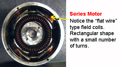
Series motor with flat wire field coils
Common Applications:
- Automobile starter motors (may draw 500+ amperes)
- Electric hoists and cranes
- Electric trains and traction systems
- Power tools (drills, saws, screwdrivers)
⚠ Warning - Runaway Risk: If a series motor loses its load (broken shaft, sheared pin), it can run away and destroy itself. The motor will accelerate uncontrollably, causing armature windings to be pulled loose by centrifugal force. Series motors should always have runaway protection.
Speed-Current Relationship:
Series motors have an inverse relationship between speed and current:
- Low current = High speed (light load or no load - dangerous!)
- High current = Low speed (heavy load - maximum torque)
Pros and Cons of Using Series vs Separately Excited (SEPEX) DC Motors
Series DC Motor
✓ Advantages:
- High Starting Torque: Ideal for traction applications (trains, cranes, elevators)
- Simple Design: Fewer components, easier maintenance
- Self-Regulating: Speed naturally decreases as load increases
- Low Cost: No external field power supply needed
✗ Disadvantages:
- Poor Speed Regulation: Speed varies significantly with load
- Runaway Risk: Can destroy itself if load is removed
- Limited Reversibility: Must switch both field and armature
- Not for Constant Speed: Unsuitable for precision applications
SEPEX/Regen/Shunt Motor
✓ Advantages:
- Excellent Speed Control: Precise speed control over wide range
- Stable Under Load: Maintains constant speed despite load changes
- Easy Reversibility: Simple to reverse direction
- Better Efficiency: Field excitation can be optimized for conditions
✗ Disadvantages:
- More Complex: Requires separate field power supply
- Lower Starting Torque: Not as strong as series motor at startup
- Additional Controls: Needs external speed controllers
- Higher Maintenance: More components to maintain
Quick Selection Guide:
Choose a Series DC Motor when:
- High starting torque is essential
- Speed variations under load are acceptable
- Applications: Traction systems, cranes, hoists, starter motors
Choose a Separately Excited (SEPEX/Regen/Shunt) DC Motor when:
- Precise speed control is required
- Stable speed operation is essential
- Applications: Industrial machinery, robotics, manufacturing equipment
Series Motor
Flat wire field coils
Few turns, heavy gauge
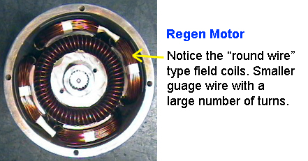
Shunt/Regen Motor
Round wire field coils
Many turns, fine gauge
Need help determining which motor type is right for your application?
Contact our technical team for personalized recommendations.